Posts

Showing posts from 2013

XMOS multicore-microcontrollers

Image
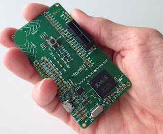
Lets go through another new trend in the ever evolving embedded systems development field. We see a huge leap in multicore processors.The number of cores extend from 2 to 16 or even more. But such a trend was never observed in micro-controllers which forms the heart of many Real time embedded systems. Such systems are self contained and are built and tested for limited but fail proof applications. A multicore environment didnt find any taste here. But as systems got complex and upgradation or adaptations become necessary within very limited time gaps, even microcontrollers needed to be flexible or more powerfull. The need for time critical embedded devices boomed up in military, aerospace, multimedia or even in consumer electronics field. Conventional microcontrollers have limitation in their I/O response time, task completion time, flexibity and peripheral support  XMOS is a fabless semiconductor startup from 2005 with the vision of configurable processing in multicore microcon

Highspeed Serial I/O

Image
Serialisation has become the order of data communication in these days. It seems like that parallel transfer is in oblivion. Nowadays, whatever new method of data transfer is introduced, it seems to work using various pairs of serial data lines in one or other form. Some of the best examples are USB, HDMI, Firewire (ieee 1394),PCIe, SATA, Ethernet, MIPI interfaces (DSI, CSI) etc.. During the old days it was considered parallel transfer could give more throughput. To some extent it was true. A parallel transfer could take a complete byte, word or quad word at a single clock to the receiving device, whereas a bit could only be transferd at a single clock edge in  a serial line. From old days itself serial transfer co-existed in form of USART, UART, SPI, I2C etc, but was limited to very small clock rates for small speed peripherals. By then, parallel method dominated for chip to chip and box transfers like ISA, SCSI, PCI, PATA IDE etc. But as clock rates increased , some problems wi

Online Electronic Shops in India

Electronics hobbyists are always in need of new parts , boards, components for their Do iT Yourself (DIY) projects. The industry is overwhelmed with various vendors, products,models etc:- Sometimes we find extremely difficult to purchase an exact part number of a product here in india. So hereby its an effort to list out some of the electronics shop websites  i found useful. Most of them are very simple to use and provide good service. Payment methods vary from Online Cash payment to COD. Many websites provide free shipping if total purchase is greater than a particular amount (500 INR mostly). So it is good to check with all of them.  Below is the list.. Will be updated as per i come across some new shops..  http://in.element14.com/ http://kitsnspares.com/ http://www.rhydolabz.com/ http://www.9circuits.com/   http://www.probots.co.in/ http://www.embeddedmarket.com/ http://www.hobby2go.com/ http://www.electroncomponents.com/ http://www.ventor.co.i

Potentiometer to Web

Image
Hi all.. lets do another beautiful DIY... Goal  To read voltage from a potentiometer in real-time and display in a web page dynamically. So.. the goal seems completely dump and does no good job.But the learning curve involved will introduce into many Linux concepts, hardware setup, troubleshooting extents from micro-controller programs to html/php code. Steps 1. Continuously read from analog input of Arduino where potentiometer is connected. 2. Send the value to Raspberry Pi via UART port. 3. Raspberry Pi reads the data and appends and writes it into a file. 4. Make an Apache server run in Raspberry Pi. 5. A combination of simple html file, a php code, and ajax script together does the job of    updating the webpage with latest value from file. 6. Forward the raspberry server to internet and watch the realtime variation of pot value in webpage. Okie.. so lets get started... Hardware Setup.. Yep.. a Raspberry pi and Arduino UNO R3 connected over UART (serial) using a

Designing with FPGA

So.. again its a bit of technology.... lets discuss.. Start Bit.... FPGAs.. or Field Programmable Grid Arrays... awesome things.. but complex to understand and start with... So a small write up like this would be nice at least for some one who is struggling to get a start with FPGA programming in Verilog/VHDL. Data bits  ..   FPGAs in its simplest form is just a Digital IC with few basic digital logic blocks arranged in repeated order along with some interconnecting fabric. So a user can rearrange or connect these blocks in different fashion to bring up any digital functionality. This rearranging can be done using a Synthesis tool  based on the User logic defined using a Hardware description Language (HDL) like VHDL/Verilog, System verilog etc..   So it is just like a bread board with fundamental digital blocks like FFs, MUXes, LUTs, Block RAMS, Shift Registers, Clock Buffers and much more. All these are at the disposal of FPGA designer for his imagination. So the glamour par

Arduino Starter

Image
Even though whopping amount of blogs and tutorials are available about Arduino and its applications, i though about leaving a small note on how to start with Arduino. For the noob . What is Arduino...?    Arduino hardware is nothing different than an ordinary Micro controller. All Arduino boards contain an ATMEL controller with USB connectivity for programming and debugging. So.. why is this Arduino hype...? I know micrcontrollers exists for more than 35 years.How is this different ? Yes... arduino is different in the sense by which user interacts with it. Or in other words.. the arduino development software is so simple and self explanatory for any one with basic coding and hardware skills. Arduino IDE just provides an abstraction such that if user wants a time delay in his program, he can just call a built in function and pass the time delay value. User is taken away from the hectic need of understanding the timers in microcontroller and the math required to produce the delay

Bidirectional 3.3v 5v Level Shifter

Image
Hi guys.. welcome to another simple DIY project... Lets make a level shifter, which will just shift a 5v data line to 3.3v or vice versa... Okie why we need such a shifter..  ? or what is this stuff actually.... ? We run around huge bunch of devices that run in various voltage levels.. for example Raspberry Pi runs in 3.3v, and its all GPIO I/O pins are at this level, even though we provide a 5v USB input. And so it is not tolerent to 5V input levels from another device or sensor modules connected to it over I/O pins using SPI, UART, i2C... whatever.... Another example is Arduino UNO which runs in 5V, normally is driving all its I/O at 5V levels.  So interfacing boards at different I/O voltage levels requires a level shifter. Simple voltage divider circuits can help for an extent.. but they dont provide low voltage  device protection or bidirectional shifting. Wait a minute ... Bidirectional... what is it ? Okie.. some communication protocols like i2C are bidirectional,

A word on Software Defined Radios (SDR)

Software Defined Radio (SDR ), resembles the techniques for creating software blocks of functional radio for reception/transmission. The concept extends from plain AM/ FM to Wi-Max/LTE radio transceivers and beyond. In other words, software defined radio (SDR) is defined as a radio in which the digitization is performed at some stage downstream from the antenna. Then the radio can use flexible and reconfigurable functional blocks for the implementation of digital signal processing algorithms. As technology advances, the digitization might be at, or very close to the antenna, such that almost all the radio functionalities are realized using software using high speed and reprogrammable digital signal processing engine             The old age radios had everything, from RF tuner to A/V detection in complete anlog domain with limited controls based on some varying resistance or impedance. The current radios consist of a mixture of analog and digital building blocks. The radio freq

Glow/Dim an LED using Rasp Pi

Image
This is an introduction to PWM generation with Raspberry pi using Python. We all love blinking LEDs. Setting the GPIO pins  high or low to lit or off LED seems so simple. But creating a dim/glow LED requires a little bit info about PWM generation.Simply PWM is all about varying the percentage of duty cycle of a square wave. Duty cycle means the diff between ON time and OFF time in one cycle of a wave. Duty cycle refers to the actual work done time in a single cycle, which is the ON time. We can say a DC signal is '100% ON time wave or has 100% duty-cycle. Paradox : DC signal has 0% OFF time, so we can't call it a wave ... :) Okey... lets start.. Raspberry has particular numbers of GPIO pins which could be used for this experiment. And we would use python to code with...So let us first write the program and discuss the logic... Assuming you are working through SSH to conect to your Pi. And no GUI is available...Login to R pi.. and assuming home folder as working d

RTL-SDR as source with GNU Radio for WFM reception.

Image
Hi all... This is about using the poor man's SDR dongle ( RTL2832U ) with GNU Radio to receive Commercial FM stations ( Wideband FM stations)... Installation of GNU Radio was a breeze in Ubuntu 12.04 using the build script by Marcus Leech.. thank to him... My core 2 duo machine took 2 hours to build the whole thing... :) Being a total noob in the complex base-band world, i decided to try something for getting familiarized with GNU Radio.. Opened gnuradio-companion.. Tried out some examples. Most of them were based on USRP  SDR Transceiver. But the source block listed the support of RT2832U to be used as a source.. thanks to osmocom . So now i decided to create a WFM receiver in GNU Radio with IQ signals collecting from poor man's receiver. Hooked the SDR dongle.. checked with some similar implementations over internet.. Created a LPF, WFM receive block, GUI Waterfall Sink block, Audio Sink block. Spend a considerable amount of time in understanding all parameters

RTL-SDR with Raspberry Pi 'PiFm' project

Image
Hi all...        I was totally excited after receiving the RTL-SDR dongle, the poor man's Software Defined Radio Receiver. I hooked it up to see the beautiful spectrum of signals in SDR# software.   And it worked like awesome. The blue waterfall is just awesome.... I wanted to test the device as fast as i could...But since i live in a villlage with no Commercial FM coverage, it semed to difficult to get hold to any strong RF signals.. Still i could get some random energies in 945-960 Mhz GSM band...pretty noisy... digital data.. so not much to be heard to... After some random browsing, i came across a beautiful project to make the Rasp Pi transmit in Wide Band FM mode. The project name is PiFm . It is a nice simple example of SDR transmitter. So without any hardware for FM modulation, a 300 lines C code modulates the DPLL output of Pi's ARM Processor with respect to the digital music data from a wave file. "Kudos to the guys who did it..". The output comes at